Voltage In Combination Circuit. That is the voltages drop across each resistor in the series portion of. With respect to a common point or ground, usually 0v, or it could be across a dual supply, for example ±5v, or ±12v, etc.
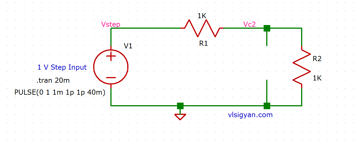
2R1C Combination Step Input Voltage Response RC Circuit from vlsigyan.com
Use the diagram to answer the following questions. True or false a voltage divider network is actually a combination circuit because the load is connected in parallel. Rtotal = r1 + r2 + r3.
A Somewhat Similar Question Asked On So.
Consider the combination circuit in the diagram below. The voltage drop on this part of the circuit was thought to be 21 v. There are 10 questions in this part.
The Issue I Have Is That Voltage Is Calculated Differently Among Parallel And Series Circuits.
+ 1/rn) when resistors are in series: Reducing a complex combination circuit. The result would be that the voltage would be equal to that of a single battery (provided they all have the same voltage, which if they didnt would be another issue).
Being A Parallel Circuit, The Voltage Across Every Resistor Is The Same As The Supply Voltage:
Notice that the two resistors r 1 and r 2 are in parallel with each other. Voltage divider circuits are useful in providing different voltage levels from a common supply voltage. At first glance, this circuit falls under neither of the two configurations discus sed earlier—series nor parallel—rather it contains a combination of the two.
A Circuit With A Voltage Source And 3 Resistors In Parallel.
Once you have the current, calculate voltage for the individual resistors by multiplying the current by the resistance. The voltage drop across the components in a combination circuit act according across each group of components as if they were in an individual series or parallel circuits. When resistors are in parallel:
Voltage Drops Add To Equal Total Voltage.
The multiple branch lines in a circuit mean there are several pathways for the charge to move to the external circuit. Rtotal = r1 + r2 + r3. With respect to a common point or ground, usually 0v, or it could be across a dual supply, for example ±5v, or ±12v, etc.
What Is The Voltage In Greece . Greece operates on a 230v supply voltage and 50hz. In greece the standard voltage is 230 v and the frequency is 50 hz. Current approaches to religion in ancient Greece Papers from writeskills.ning.com Manufacturers take these small deviations into account. What kind of converter do i need for greece? Type c and f power outlets.
What Is Flow Of Electricity . Electricity can be moved long distances more efficiently using high voltage. Static electricity is the build up of electrons on an insulator. Pin on Electricity and from www.pinterest.com This definition is used by some electric companies, probably in a misguided attempt to combine definition 2 with definition 3. Power automate or microsoft flow is destined to collect data over diverse platforms to record the brand presence amongst the targeted audience. Alternating current (ac) and direct current (dc).
What Is 100 Watts In Volts . Once you have that information, the calculation is simple for a dc circuit: In a 1 amp circuit, you have 1 watt per volt. HQST Flexible Solar Panel, 100 Watt 12 Volt from www.desertcart.sg The power p in watts (w) is equal to the squared voltage v in volts (v) divided by the resistance r in ohms (ω): Its known that power is the product of current and potential i.e p = iv v = ir( from ohm's law). P (w) = v (v) x i (a) = 18 v x 6a = 108 watts (w)


Comments
Post a Comment